

source:Industry News release time:2022-04-13 Article author:yu Popular:pcb
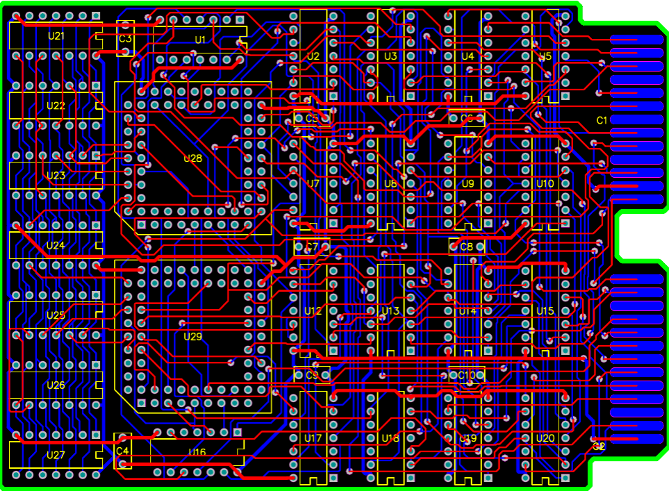
I have recently discussed this routing rule in detail in the article The Case Against Orthogonal Trace Routing in Multilayer PCBs [2], and some of the important conclusions are reproduced below. The rule of vertical wiring is that the traces on adjacent signal layers need to be perpendicular to each other to reduce crosstalk caused by mutual inductance. In high-frequency signals, crosstalk through capacitive coupling dominates, producing current spikes between vertical leads.
When the signal changes along the time, or the frequency is low (less than several GHz), the coupling capacitance interference of the vertical wiring components of the adjacent signal layers is small. In the radio frequency (RF) frequency band (tens of GHz), the interweaving of the leads produces hole resonance, and the conductor structure that is not surrounded by the ground wire will produce electromagnetic resonance at some special frequency points. At this time, even if the leads are vertical, strong crosstalk will be caused between them.
In order to eliminate interference at all frequency points, a simple and effective method is to use a multi-layer board and use an isolation layer between the signal layers. This is especially important in contemporary applications where signals are changing rapidly. When you are not sure about the coupling strength between orthogonal lines, you need to use basic crosstalk simulation software to check the vertical leads to see if the crosstalk between them is within the noise tolerance range. At this point, you need to plan the signal return path, which is a major problem in vertical routing.
2. Heat dissipation vias
This is a classic "do/avoid" rule that is often debated. Some PCB designers say they never use heat-prevention vias and have never had problems with soldering and assembly. Another group insists that thermal vias need to be used whenever each plane is connected. Who are they right?
Their views are applicable to different occasions. If you are soldering the board by hand, you will need to raise the temperature of the soldering iron tip to compensate for the soldering problems caused by the soldered vias dissipating heat from the copper layer. However, if you use wave soldering, you need to use anti-thermal vias to prevent device loosening, cold soldering, tombstones, etc., so I suggest you better bite the bullet and stick to the thermal-preventing via design.
Read recommendations:
Six-layer Immersion Gold Board (BGA)
Laminate copper-based PCB after 4L (sample)
Popular recommended products
Computer card board (four layers)
2021-04-25Six-layer Immersion Gold Board (BGA)
2021-04-27Six-layer Immersion Gold Board (BGA)
2021-05-24Single copper base PCB
2021-04-27High frequency PCB
2021-04-27Network communication board (sixth floor)
2021-04-29Six-layer Immersion Gold Board (BGA)
2021-05-24Six-layer Immersion Gold Board (BGA)
2021-04-27Mobile phone template (six layers)
2021-04-27High frequency PCB
2021-04-27Aluminum substrate (double-sided)
2021-04-27Single-sided double-layer AL base PCB
2021-04-27Six-layer Immersion Gold Board (BGA)
2021-04-27High frequency PCB
2021-04-27Silver oil perforated plate (double-sided)
2021-04-27Six-layer Immersion Gold Board (BGA)
2021-05-27Six-layer Immersion Gold Board (BGA)
2021-05-27Six-layer Immersion Gold Board (BGA)
2021-04-27Six-layer Immersion Gold Board (BGA)
2021-05-27Laminate copper-based PCB after 4L (sample)
2021-04-27High frequency PCB
2021-04-27Display board (six layers)
2021-04-27Six-layer Immersion Gold Board (BGA)
2021-05-27Six-layer Immersion Gold Board (BGA)
2021-04-26Mobile phone board
2021-04-27Mobile phone board
2021-05-27Six-layer Immersion Gold Board (BGA)
2021-04-26DIP plugin
2021-05-27Six-layer Immersion Gold Board (BGA)
2021-04-26Six-layer Immersion Gold Board (BGA)
2021-04-26SMT stickers
2021-05-27SMT stickers
2021-05-27Six-layer Immersion Gold Board (BGA)
2021-04-26DIP plugin
2021-05-27Related Information
Composition of PCB
2024-09-29What is the difference between PCB and PCBA
2024-09-10PCB usage tips
2024-08-20Why do the circuit boards are green
2024-08-12How to clean the aluminum substrate?
2024-08-06Maintenance of Chemical Copper Plating Solution on PCB Board
2024-07-22single-sided PCB board and double-sided PCB board
2024-07-15PCB board production process flow
2024-07-09PCB CTI level
2024-07-01Via technology in circuit board factory.Automotive Electronics PCB
2024-06-25The role of FPC flexible circuit board solder mask
2024-06-18Detailed explanation of PCB board sampling production process
2024-06-11pcb v-cut depth standard
2024-05-27Multilayer Printed Circuit Board.What is the eq of PCB
2024-05-20The relationship between PCB safety distance and voltage
2024-04-22SMT surface mount processing.Hybrid circuit board PCB
2024-04-15PCB enterprises should pay attention to SMT matters.Electronic components PCB
2024-04-03PCB - the core building block of electronic products.Automotive Electronics PCB
2024-03-25PCB - the bridge and link of the electronic world
2024-03-18How to define high-frequency and high-precision circuit boards.Industrial Electronics PCB
2024-03-11USB PCB interface layout and wiring requirements
2024-01-22Electrolytic capacitor PCB.Steps for using PCB pins
2024-01-15Automotive ElectronicWhat aspects should be considered when processing and manufacturing PCB boards?
2024-01-08Electrolytic capaciWhat is the difference between a gold-plated circuit board and a gold-plated one?
2023-12-25When grinding PCB boards, attention should be paid to.Oscillator (belonging to crystal) PCB
2023-12-18Industrial Electronics PCB!What precautions should be taken when copying and grinding PCB boards
2023-12-11Do you know who is more suitable for LED direct display, regarding the difference between PCB board
2023-12-05Aluminum electrolytic capacitor PCB.What are the standards for selecting PCB boards
2023-11-27Surface Mount Technology (SMT) Phase PCB
2023-11-20Oscillator (belonging to crystal) PCB.The main functions of PCB board
2023-11-13
CopyRight © 2007-2025
粤ICP备2021061255号

Address:
1205, Floor 12, Building 3, Chuangyi Office Building, No. 110, Ziheng West Road, Jinsha Community, Kengzi Street, Pingshan District, Shenzhen, Guangdong, China

Tel:
+86-755-29662580

Email:
sales@victoriapcb.com

PCB

PCBA
Service
Process
 Tel: +86-755-29662580
 Email: sales@victoriapcb.com
 中
中 current position:


